USB Ultra Infrared Receiver to remote
control and power on/off the PC
Today, another
interesting infrared receiver solder guide for the PC is finished.
Who like to control the PC or HTPC comfortable from the sofa, can solder different IR receiver types for commercially available universal remote controls.
There are some self building guides in the ocinside.de modding section for several years
and today a new special infrared receiver soldering guide for the PC is published.
After the
extended guide for the infrared receiver with hardware side function
to remotely switch the PC ON or OFF as full USB variant with
the name "USB Ultra infrared receiver" or briefly "USB Ultra
IR" a new version 2.0 is now available.
The new USB
Ultra infrared receiver v2.0 was - contrary to the previous version - extended
by some electronic components and offers thereby new functions and some
improvements.
The USB Ultra IR v2.0 indicates now with a red LED the receipt of infrared signals.
A green LED indicates that a power on/off signal is received which was programmed before.
Furthermore a new TSOP receiver unit is used, which is more sensitive and more energy efficient.
Last but not least the USB wiring was optimized, so that the operation also with all newer PCs and current motherboards should be no problem, since the USB data lines are now reduced to 3.3V instead of 5V.
All other functions are explained exactly on the following pages, thus much pleasure with reading and soldering.

Where is the sense of an infrared
receiver at the PC ...
If you like to
use the PC to watch television or S-VCD, DVD, DivX files or if you like to
build a
complete J-box II project with LCD display, etc. for the HiFi rack, you would also like to enjoy the comfort
to remote control all applications of this PC easily from the sofa.
complete J-box II project with LCD display, etc. for the HiFi rack, you would also like to enjoy the comfort
to remote control all applications of this PC easily from the sofa.
So the
first Luxus/Lowcost infrared receiver circuit was published
in July 2002 on ocinside.de and the goal was
a remote controlled PC with a connection to the serial port.
The next development was the USB infrared receiver guide to control the PC with a conventional remote control unit,
but with an USB connection instead of using the serial port.
So, there're a few ways to manage this very comfortable - may be with the well-known Luxus IR, Lowcost IR,
USB IR, or with the new USB Ultra infrared receiver which is now also offered as a complete kit in the Fanshop.
That is new at the USB Ultra infrared
receiver 2.0 ...
Well, but what
can the USB Ultra IR receiver contrary to conventional infrared receivers ?
Very simple - on the one hand it receives the signals to send it to the PC Software (like Girder, WinLIRC, etc),
but on the other hand it can also compare infrared signals to power off or power on the PC.
So it's possible to remotely power on the PC (ATX Power Button, WoL, etc.), watch a film or hear some music and
hardware side power off the PC.
The PC can thus be completely controlled with a usual remote control unit (38 kHz RC-5) e.g. of the television,
or another HiFi component and/or all universal remote control units.
And since the latest version 2.0 this is additionally shown with two light emitting diodes.
Take some
pretzel sticks or chips, loll on the sofa and watch TV, hear music, etc. :-)
These units are necessary ...

1x Vishay TSOP 31238 (38 kHz
infrared receiver)
1x Atmel ATtiny45-20PU (this IC have to be programmed like in the Fanshop !)
1x Atmel ATtiny13V-10PU (this IC have to be programmed like in the Fanshop !)
2x 8-pin IC-Socket
1x optoelectronic coupler CNY17-2
1x 12MHz quartz
2x Zener diodes 3.6V
1x red low-current LED
1x green low-current LED
1x 4.7µF / 16 volt capacitor (Elko or Tantal) vertical construction
1x 100nF capacitor (ceramik, layer or multilayer) vertical construction
2x 22pF ceramik capacitors vertical construction
3x 1.5 K resistors (0,25 watt)
2x 68 Ohm resistors (0,25 watt)
1x 390 Ohm resistor (0,25 watt)
1x 2-pole strip for the jumper
1x Jumper
1x Printed circuit board (PCB); approx. 6.8 x 3.2 cm with 25 x 12 holes is sufficient
1x USB A-Plug
1x approx. 1 meter shielded data cable with at least 4 pins
(alternatively a finished USB cabel with A-plug like in the fanshop kit can be used)
1x 2-pole cable approx. 1,5 meter
The function and the circuit diagram of the USB Ultra IR receiver
v2.0
The USB Ultra IR receiver v2.0 functions ...
First I would like to explain here briefly, what the USB Ultra IR
v2.0 receiver makes at all.
When the TSOP31238 receives a RC5 coded infrared signal, it gets
on the one hand directly to pin 7 of the
programmable ATtiny45-20PU Atmel IC.
This Atmel IC, is clocked in the circuit with a 12 MHz quartz and
provides a communication between the Infrared receiver and the PC, so that this
signal can being processed by infrared receiver programs like Girder.
The 1.5 K resistor is as Pullup resistor between the negative data
line and the 5 V power supply
of the USB connetor to stabilize the logical signal.
The two 3V6 Zener diodes with the 68 ohm resistors limit the
voltage at both USB data lines Data+ and DATA-,
so that they finally only get approx. 3.3 V instead of 5 V from the Atmel IC.
Further a red low-current (power saving) control LED is soldered
with a 1.5K resistor between DATA (Pin3) and +5 V VCC (Pin2) of the TSOP
infrared sensor.
The signal goes however not only to the PC, but also to the second
ATtiny13V-10PU Atmel IC,
which have to be programmed with a special firmware before and has the
following function:
- If the Jumper J3 is put in, the AVR IC save the valid RC5 code
of an infrared remote control in the integrated
EEPROM to compare it.
The desired key on the remote control for switching on and switching off the PC
is thus programmed.
As soon as a valid RC5 signal of the remote control arrives, a green low
current LED with a 1.5K resistance and the opto coupler with a 390 ohm resistor
is supplied with power.
- When the Jumper is then taken off, the small 8-bits AVR RISC
processor compares all incoming signals
with the stored signal of the EEPROM and if the two signals are equal, the opto
coupler is supplied with power.
Unfortunately the ATTINY13V-10PU Atmel IC cannot be programmed any
longer as simply as the AT90S2323 IC
in the USB
infrared receiver guidance, since Atmel changed some special Fuse bits which
prevents a programming
of the firmware with conventional ISP prommer (ISP = in system prommer).
For this reason I program the firmware with a more complex Atmel programmer
directly on the ICs and
offer them programmed as kit in the Fanshop.
Here I set also all fuse bits that this Atmel IC needs no external quartz or
resonator.
The opto-coupler and the solution to switch the PC on and off ...
After careful consideration and numerous tests I decided to pass
the switching signal of the Atmel IC
over a 390 ohms resistor to an opto coupler, which has the task, to connect its
2-pole output (pin 4 & pin 5),
as soon as the input pins (pin 1 & pin 2) got the switching voltage.
This output could be connected e.g. with a WoL (Wake on Lan) connector, where
we can also get the 5 Volt power.
However, then one would not have the ingenious advantage to additionally switch
its PC off.
For this reason I decided for better solution, where the output of
the opto coupler is connected directly
with the PC power Button parallel to the power Button connection of the
motherboard.
The circuit get its necessary 5 V power supply over an USB cable, because
current ATX Mainboards supplies the
USB port also with power when the PC is switched off if this is activated by a
Jumper (+5VSB) or in the BIOS.
If this is not the case, or the PC has no necessary PowerOn feature, it's
possible to get the 5 Volt power
over a small external 5 Volt regulated power supply unit.
To separate the 5 V USB power supply you could cut, for example, the VCC
connection from Pin8 of the ATTINY45 to Pin8 of the ATTINY13V or connect the
complete circuit simply to an active USB Hub with external power supply to
supply the circuit continuously with power.
Alternatively it would be possible to get it from the ATX power supply
connector directly. However a wrong wiring
would forgive no errors, therefore I would not like to continue here with a
detailed explanation.
A PC ATX PSU pinout can be found in our Forum - e.g. in this PC
power supply pinout topic.
It's easy to check if the USB port gets power when the PC is
switched off, with an optical Mouse at the USB port.
Because the lighting of the optical scanning continues in this case if the PC
is switched off.
Of course it's also possible to measure the voltage of the USB port.
And who would like to vary a little bit, can use the WoL connection of the
Mainboard.
Here is the circuit for the USB Ultra IR v2.0 guide ...

Here is the connection diagram of the old
USB Ultra IR v1.1.
Additionally I have also build another variant for the operation
of the power AND the reset button.
Here is a link to the special
POWER and RESET circuit.
If you would like to build this, you can order e.g. the USB Ultra IR v2.0 kit
in combination with the normal
Ultra IR kit and develop hereby the special reset & power circuit.
The soldering guide for the USB Ultra IR receiver
Enough theory, lets go to the practice ...
Here is a picture of the PCB layout with all construction units
for easy soldering.
Just watch it comfortably while your soldering iron (15-25 watt) is heating-up.

Here is the old
USB Ultra IR v1.1 solder guide.
The correct position of the construction units ...
First we begin to plug in the construction units as explained on
the 25 x 12 holes of the printed circuit board (PCB).
Bent the pins under the PCB a little bit, but please DO NOT shorten the pins, yet !!!
It is important that the small notches of the two IC sockets and the notch of the opto coupler with 6 pins
are showing upward.
The new Tiny45 IC got one small point instead of the notch to show the right direction.
It is also necessary to pay attention to the polarity of both zener diodes (Z-diodes) and both Light Emitting Diodes,
whereby the black ring of the Z-diodes have to show up to the direction of the IC notches.
The polarity of LEDs is shown on a picture later on.
Furthermore you must absolutely pai attention to the correct polarity of the small yellow 4.7 µF tantal capacitor,
where the positive pin must show likewise upward like the IC notches!
(beneath the 16 is a small plus (+) symbol to indicate the polarity of the construction unit).
With the other construction units there is no polarity, so that only the correct position is important there.
Here again a picture with the different tantal capacitor designs
and the polarity:

Here is a picture of the Z-Diodes / Zener Diodes polarity:

And here is a picture of the light emitting diodes polarity,
whereby the shorter pin with the larger connecting surface and the reflector
within the light emitting diode is the cathode/GND/ground/-/VSS.
The longer pin with the smaller connecting surface within the light emitting diode is the anode/+/VCC:
The longer pin with the smaller connecting surface within the light emitting diode is the anode/+/VCC:

Once again a photo with the right positions whereby we place the
LEDs later:

When all construction units except the LEDs are fixed attached, it
continues with the lower surface.
The 22pF capacitors of the quartz are not absolutely necessary but they are the
load capacity for the quartz and should be soldered to a quartz.
I've published another mirror-inverted picture so that one does not have to
turn always the PCB for the
detection of the right construction unit.
Here's the mirror-inverted
view ! for better
orientation on the lower surface ...

rot = red, weiss = white, grün = green, schwarz = black, Zum
Mainboard = to the mainboard power switch
spiegelverkehrt = mirrored
Correct bending and pinch off the pins ...
On the basis of the photo one should bend now simply all pins of
the construction units and pinch off the pins,
whereby one again should make sure 100% that all construction units are on the
correct position and
as above explained also paid attention to the correct polarity.
If you make an error in this step, it's later rather difficult to out-iron -
spend some time to bend all pins
as shown and cut all pins in the correct length! with a long-nosed pliers and a
small wire cutting pliers.
Thus the lower surface looks like after the bending all pins:

And in such a way looks the lower surface after cutting the pins:

Now solder only the shown parts ...
First we solder only all pins on the lower surface of the PCB as
represented on the following Picture.
Please do not solder everything, yet, but first times only each pin of the
parts, since we still need the cables.
Also absolutely consider here the free spaces, where no connection may be.

Now we solder still another small bridge (from one before cutted
pin) to the right side.
Simply bend one side approx. 2mm, put the wire, cut the correct length on the
other side and then solder,
so the bridge can not slip when soldering.

Now another solder bridge is added in the center of the two ICs.
Here we can also use simply a piece from the material cutted before.

Solder the red low current LED and the green low current LED ...
Now it is time for the two light emitting diodes, which must be
polarized absolutely correctly,
so that they can light up afterwards.
The red LED is placed directly to the TSOP, whereby the shorter pin (-) points
to the TSOP IR receiver.
The green LED is put in near the Atmel ATTINY13V IC, whereby the longer pin (+)
is soldered to the resistor
and the shorter pin (-) to the small GND solder bridge, which we soldered on a
while ago.
I consciously soldered the two LEDs now, because who ordered the
new small IR receiver box from the Fanshop,
of course would like to see the LEDs nevertheless. And this is only possible if
the LED pins are left very long,
so that the LEDs can be seen afterwards on the top side of the box.
One should put the LED pins so far into the PCB, until the longer pin is seen
approximately 8mm at the PCB bottom.
Who does not use the IR box, can solder both LEDs directly on the PCB.
And who would like to place the PCB inside of a PC or HTPC, can use a
2-pol cable in order to attach the LEDs for example in a drive front bezel or
in a Casesticker.
On the next picture you can see the four new soldered connections
- two of the red LED in the left above the TSOP and two of the green LED right
down near the lower IC socket.
Prepare the cables ...
If you like to relax a little bit, it's time to prepare the
cables.

All cables are stripped approx. 3-4 cm, the outside shield is
separated cleanly and then all individual wires
have to be stripped and tin-plated.
It makes sense to tin all wires to get the tin later easier and faster on the
wires.
Simply hold the soldering iron to the stripped wire and hold some tin to the
other side solder.
Repeat this with all wires.
Here is a small picture sequence how to strip it correctly ...

Put the cables into the right PCB hole ...
The small cable, which I could not unfortunately avoid in the
layout, one can get oneself simply,
cutting the USB cable or the 2-pole cable a few centimeter and taking one wire
of it.
Strip the wire approx. 2-3 mm, twine and tin-plate it as written before.
Now we put the cables with the explained colors in the correct
place into the PCB.
The four wires of the USB cable are soldered this way:
The red (VCC) cable is soldered to the middle TSOP pin, the 1.5 K resistor and the one side of the 100n capacitor.
The black cable (GND) is soldered to the Jumper and the other side of the 100n capacitor.
The white (or yellow) cable (DATA-) is soldered with the 68ohm resistor to pin 5 of the ATTiny45 IC and the
green (or blue) cable (DATA+) is soldered with the other 68ohm resistor to pin 6 of the ATTiny45 IC.

Sometimes USB cables have different colors.
Here is a table with some possible USB cable colors (just in case your cable is
NOT red, black, white and green):

The last soldering act, where the remaining connections are
soldered ...
Now we solder as explained the remaining solder joints, whereby we
must absolutely pay attention to
all free spaces (e.g. the two pins of the tantal capacitor may not soldered
together).
If you still like to solder a little bit, you're free to solder the GND shield
of the USB cable with a short wire
to a GND solder point of the circuit, but it's not necessary with same GND.

We solder the 2-pole, approx. 150 cm long cable (in the picture
brown and white) to the pins 4 and 5
of the opto coupler, which is connected later to the power Button of the PC.
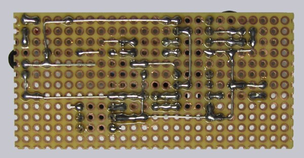
Here is a picture of the soldered lower surface ...

Insert both ICs in the right direction ...
Now insert the ICs with the IC notch (or the point) to the IC
Socket notch (in the following picture to the right),
whereby the ATTiny45-20 is alongside the quartz and the ATtiny13V-10PU is next
to the Jumper.
Afterwards we can put on the Jumper for the first programming ...

That's it, we've build USB Ultra IR-receiver 2.0 ... :-)

Now control again all soldered connections and again the correct
polarity.
It is now rather late to discover failures, but better late than never and one
can never control often enough.
The power supply unit and the USB port is secured, but it's really important to
prevent all failures.
Of course I'm not responsible for any damages.
But if you've problems with late noticed solder failures, I'll give my best to
help you by E-Mail.
First start-up of the USB Ultra IR receiver v2.0
Now we come finally to the most beautiful point of the whole work
...


No comments :
Post a Comment
feel free and ask...